Livox Mid-40 LiDAR review
Continuing on my excursion in LiDAR testing I gave a Livox Mid-40 a spin. This post sums up my experience working with it for couple of days.
Hardware specification
| Parameter | Value |
|---|---|
| Field of View | 38.4° (circular) |
| Maximum range | 230m |
| Range precision | 2 cm |
| Angular accuracy | < 0.1° |
| Point rate | 100,000 points/s |
| Laser wavelength | 905nm |
| Power | ~10W |
| Power supply | 10-16V DC |
| Weight | ~710g |
| Price | 599 USD |
The hardware specification above has been taken from the Livox user manuals available on Livox website
First impressions
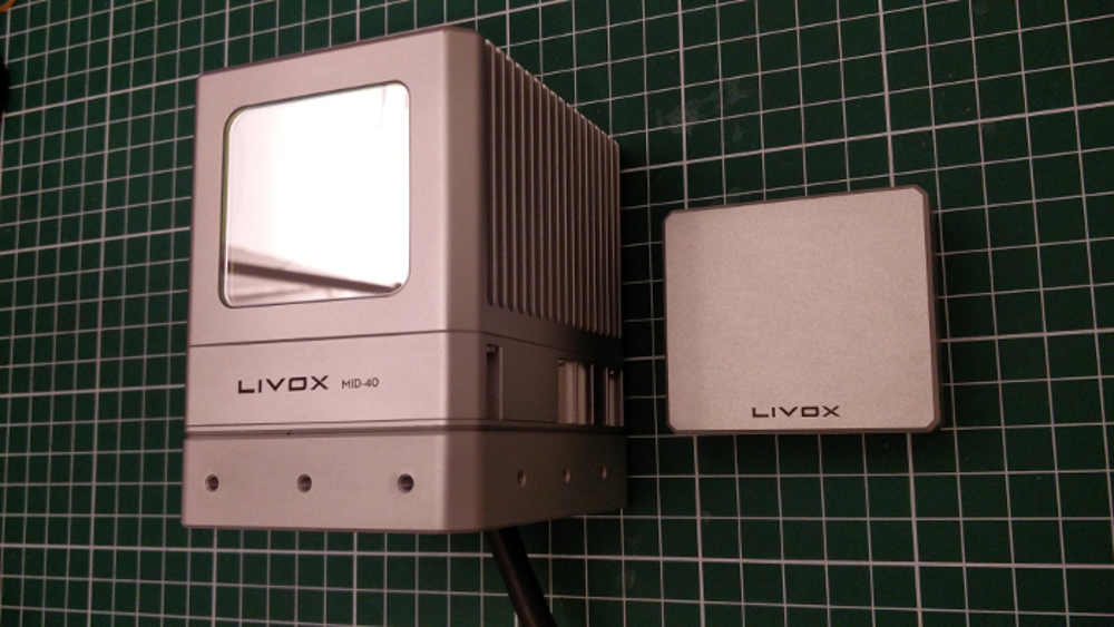
The first thing I liked about Mid-40 was the nicely machined aluminum body. The main body of the sensor comes with an attached cooling fan. The data cable is attached to the bottom of the sensor, hence it comes with an aluminum offset that allows mounting the sensor to flat surfaces. It also has a 1/4”-20 screw thread hole that makes it ideally fit most tripods.
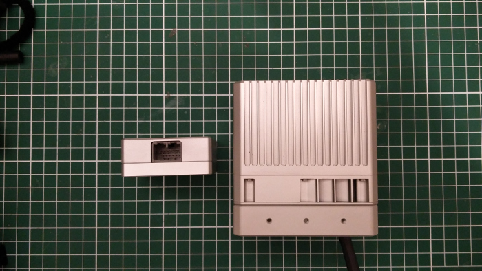
To connect Mid-40 to your setup you will be working with Ethernet. To make sure you can access the LiDAR you will need to have a DNS server that will assign the address to LiDAR (either statically or dynamically). You will find more information about it on page 13 of user manual(checked with manual V1.0).
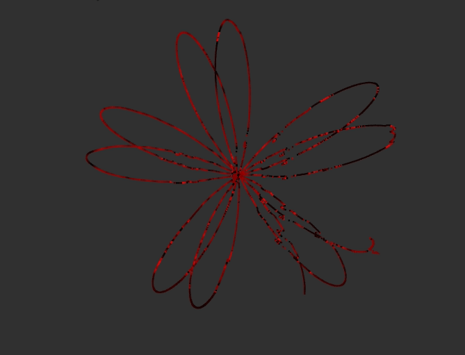
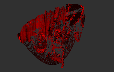
What is special about Mid-40 compared to the LiDARs you are used to is the scan pattern.
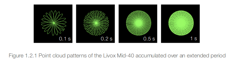
From a short research it looks to me that the scanner might be using rotational Risley Prisms. If you would like to learn more about them then this paper might be a good start.
Testing with ROS
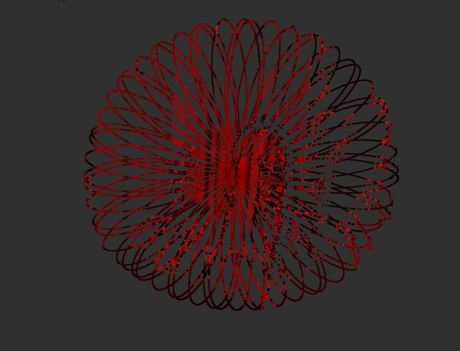
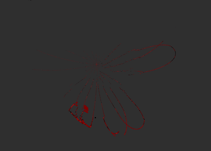
After installing SDK I run a number of test using the Livox-SDK-ROS package(commit 59f904a47). Below are some visualizations that I captured with the LiDAR being stationary and looking at a fixed scene. To show the scanning pattern i varied the decay time (controls how long received point clouds are preserved) in RVIZ visualizations.
Checking publishing rate with rostopic hz command we learn that the new scans are delivered at 20 Hz.
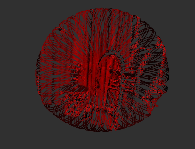
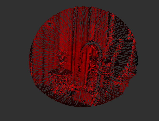
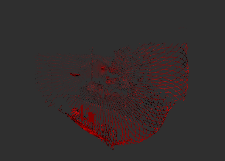
Static test in a room
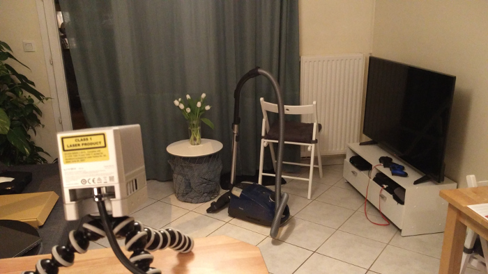
In the first test I had the LiDAR looking at the scene shown above. Below you can see the captured point clouds.
The bandwidth consumed by the scans in this scene is 1.60 Mb/s.
Looking on the scene from the side the point cloud looks as follows:
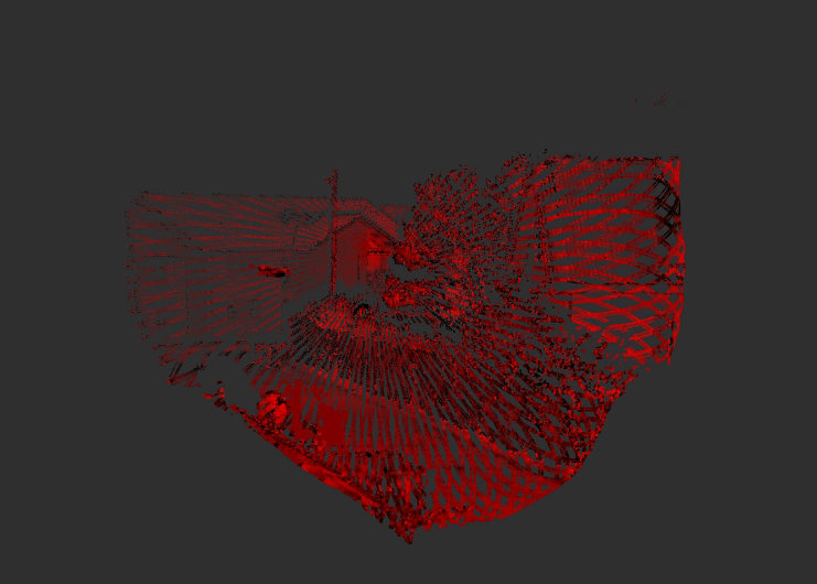
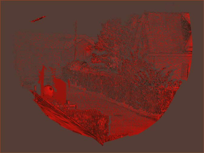
Outside test
In this test I used the sensor in the outside environment. It shows how impressive is the range and the amount of detail you can get with high enough exposure time. You can open the images in a new tab to see the at higher resolution.
Thoughts on ROS package
Working with the ROS package was a matter of downloading it, changing a broadcast code in the source file and compiling it. For a company that is just entering the market I would say that the ROS packages are in acceptable state however I would still love to see some improvements in the future:
- Change the repository directory structure. With the current structure the built code will be on the repository level, meaning after each build the repo will be in a dirty state
- Expose frame_name as a parameter so that it can be changed at launch time
- Similarly expose the broadcast_codes as parameters so that the code doesn’t have to be recompiled if switching sensors
- Rename node names to include the company/product name
- Use PointCloud2 instead of PointCloud
- Use ROS logging constructs instead of printfs
Final thoughts
I quite enjoyed working with the Mid-40. I especially liked how easy was the setup (provided you have 10-16V power supply and a router it’s basically Plug&Play). What I missed from the documentation and I think is the minimum range that seems to be around 1m. Apart from that I was thoroughly impressed with the maximum range of the LiDAR and how clean the obtained data was. The ROS package is OK for something that has been developed for a month and I’m sure it will be improved over time.
What I think will be the biggest challenge that Livox will face is the technology adoption. I tried to test it with HDL Graph Slam, however with default parameters I couldn’t get a reliable SLAM output. I think the main issue might be what I would call “time to point revisit” (a time between two consecutive measurements of the same point). Given that in most of the traditional LiDARs the same points are revisited at every scan Livox might need to open a new era of SLAM tools that will support a new scan patterns.
Update (10th of October 2019)
I think it’s high time to update this post with some of the developments that had happend since I’ve tested the LiDAR.
Loam Livox
Loam Livox is an odometry and mapping package created by Jiarong Lin. The demonstrators look quite promising and as soon as I have some spare time on my hand I’ll run an extensive test of it and post some bag files for you.
Special firmware
Livox had published a repository with special firmware. Among them we will find firmware that enables:
- Mulit-return support - this is the one I’m most excited about as it allows using the LiDAR in forestry applications
- Threadlike-Noise Filtering
- Short blind zone - decreasing the minimum range from 1m to 0.3m