Plug&Play RTK with Septentrio mosaic-X5 Dev Kit
Quite a while ago I’ve received two units of mosaic development kits from Septentrio. This blog posts sums up my experience with it and provides some insights into integrating these with ROS.
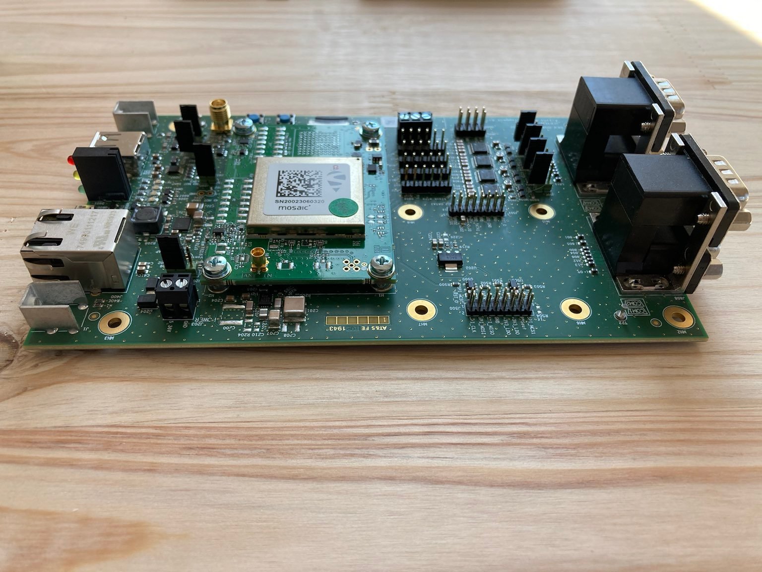
First impressions
The first thing that you notice when unpacking the module is the size of the carrier board at 10x16 cm it’s quite large, however, the core module is only 7x5 cm.
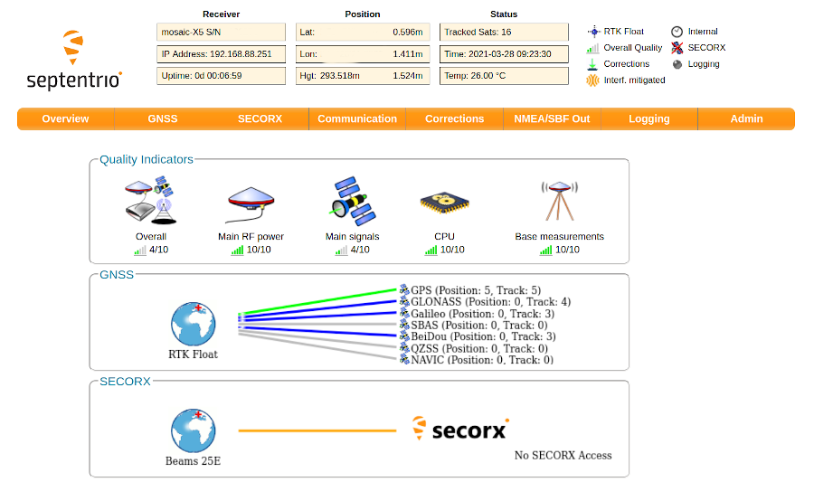
I don’t think I’ve ever used a positioning system that would be that simple to set up. This video that is less than 2 minutes explains the basics on how to connect to the module. The gist of it is you connect the receiver antenna, attach a USB cable and navigate to the local webserver, hosted by the module in your web browser (192.168.3.1) and poof the interface is there:
Need to set up the module to output NMEA sentences on a USB port? Simple! Go to NMEA/SBF, select connection type (USB), desired serial port, message types (e.g. GGA, RMC) and interval you are interested in and you are good to go. The dev USB port on Septentrio (the micro-USB port on the carrier board) creates two serial ports that you can use on your target machine. Being able to configure UDP or TCP streams is also an interesting option.
The base station-rover setup is very easy as well - the instructional video has less than 3 minutes, once you know what you are doing this setup likely takes way less than a minute.
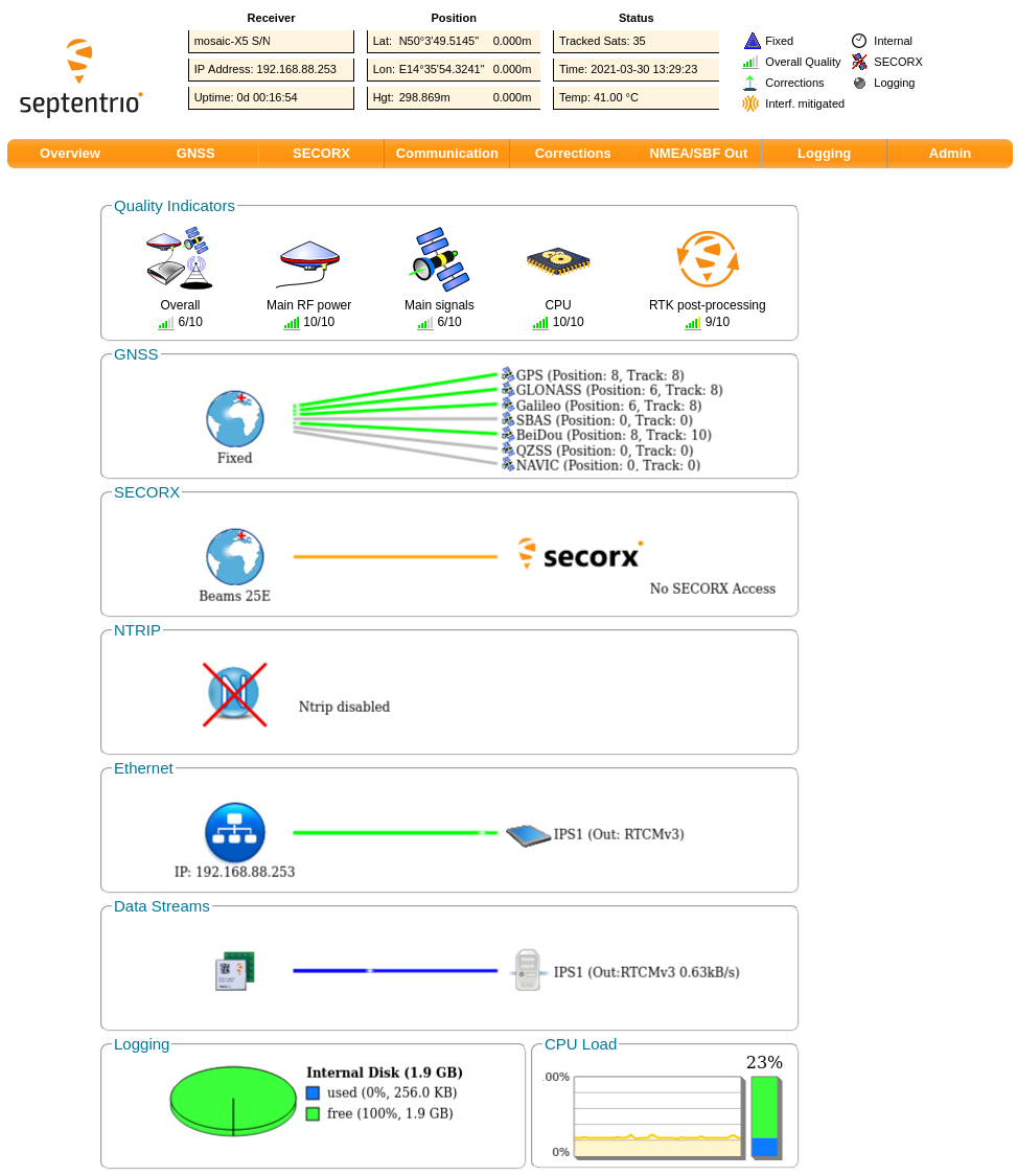
What is also worth noting is the number of carriers that are supported. In my test the base station was receiving position from 4 systems: GPS, GLONASS, Galileo, BeiDou:
Testing
Hardware setup
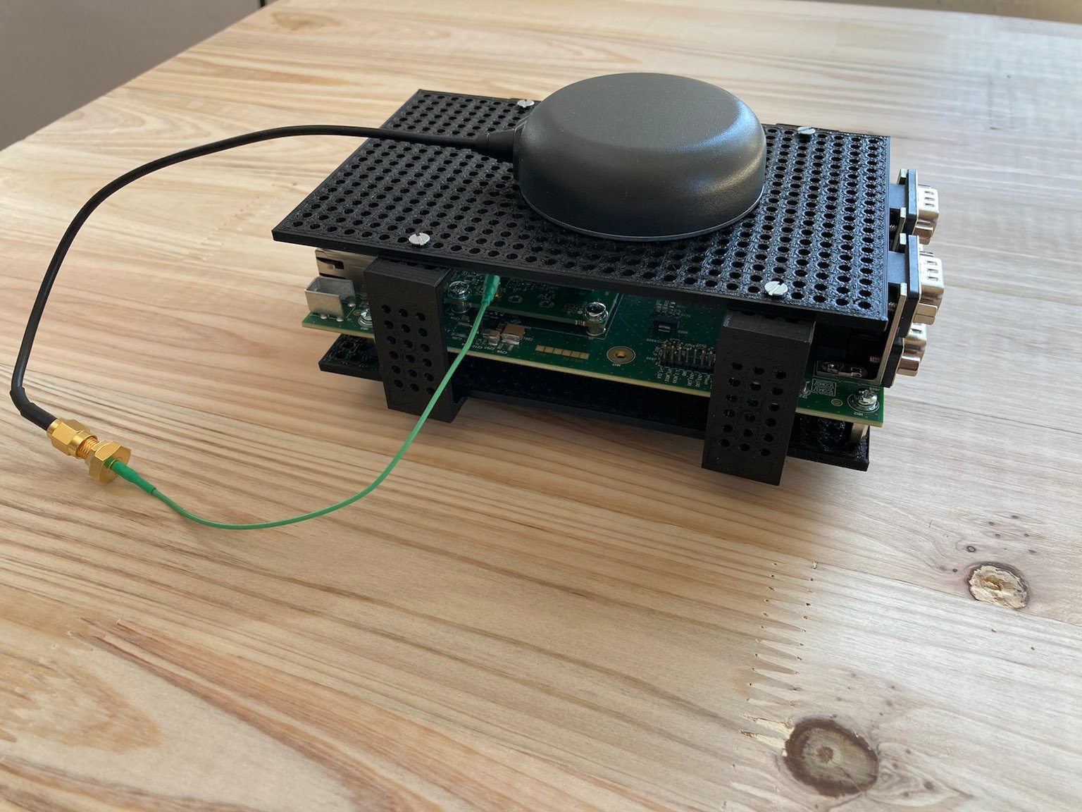
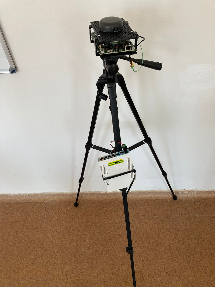
To run some integration tests with ROS I’ve decided to make two tripods, each carrying a Septentrio mosaic-X5 kit, antenna, battery and a wireless router. One of the tripods is used as a base station, while the second one is used as a rover (I’ll carry this one in hand when testing). Additionally, the rover has an IMU with a magnetometer attached next to the antenna.
As I mentioned in the previous section I’ve set up an NMEA USB stream for my tests. To do this I created a new udev rule for the modules (the full workflow being similar to the one described in my static USB tutorial):
KERNEL=="ttyACM*", ATTRS{idVendor}=="152a", MODE="0666"
I’ve set the two MikroTik routers to PTP Bridge mode, making sure the base station is outputting correction on TCP port and that the rover module is subscribing to them.
ROS setup
ROS setup is quite classic for mobile robot setup using navsat_transform_node, robot_localization, imu driver and navsat_nmea_driver. Let’s go over the most interesting bits of my test setup.
Navsat driver
I’ve decided to use the nmea_navsat_driver for reading NMEA data from Septentrio through a serial port. The reason I opted for this is the simplicity - I could set it all up and be testing in no time. Or so I thought until I’ve discovered that nmea_navsat_driver has this thing that will prepend the frame_id you provide it with /. This in turn breaks the latest version of robot_localization. This seems to have been fixed in Noetic but is a wontfix for Melodic.
Localization
Since for quite a while I’ve wanted to create a handheld device for some data capture (hopefully more info coming soon) I’ve decided on the following assumptions:
- Single EKF - for any mobile robot setup you would most likely use a dual EKF setup but since I don’t have any sensor providing continuous measurements in planar axes a single EKF instance should be sufficient
- IMU fusion for orientation and heading - could be useful in the future when I start pointing my setup at things
- WGS84 -> fixed frame transform - I’ve set up robot_localization to publish this transform so that mapviz would display my ‘robot’ in the global frame
Test results
For this blog post I’ve performed two experiments:
- Static test - both rover and the base are placed in a static location for 15 minutes, then for around 10 minutes we run the localization stack and observe changes to the local position
- Dynamic test - trying to trace a pattern drawn on the ground
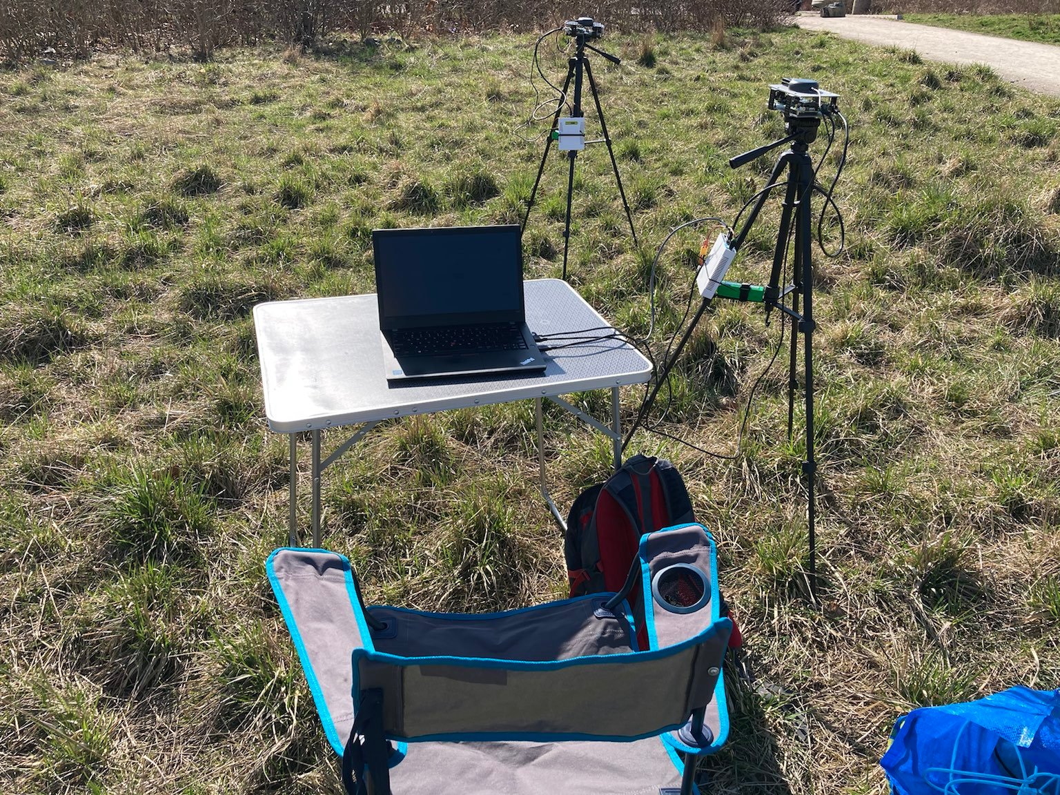
If you are a robotics engineer and not getting enough sun exposure then I highly recommend testing GNSS modules, this setup allows for some proper vitamin D boost:
Static test
At first, I was thinking of setting up a 10x10cm grid in mapviz and test if the base frame in the local coordinate system ever moves outside the grid cell during the test. Boy, was I pessimistic…
The test I actually performed was launching the robot_localization, causing the local frame to be at the initial position of the rover receiver, and letting it run for around 10 minutes without touching any tripods. Here is the X and Y position (thanks PlotJuggler!):
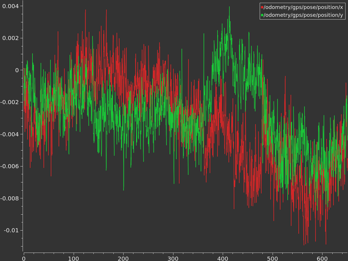
As you can see in the graph, throughout the test the position didn’t significantly move. The lowest measurement on the above graph is -0.010895 m (that’s < 1.1 cm). The ground I’ve set up on wasn’t flat and it was quite windy. I have no idea if these factors could cause the module to shift slightly but the result is amazing as it is, working on wheeled-mobile robots I would not need higher precision anyway.
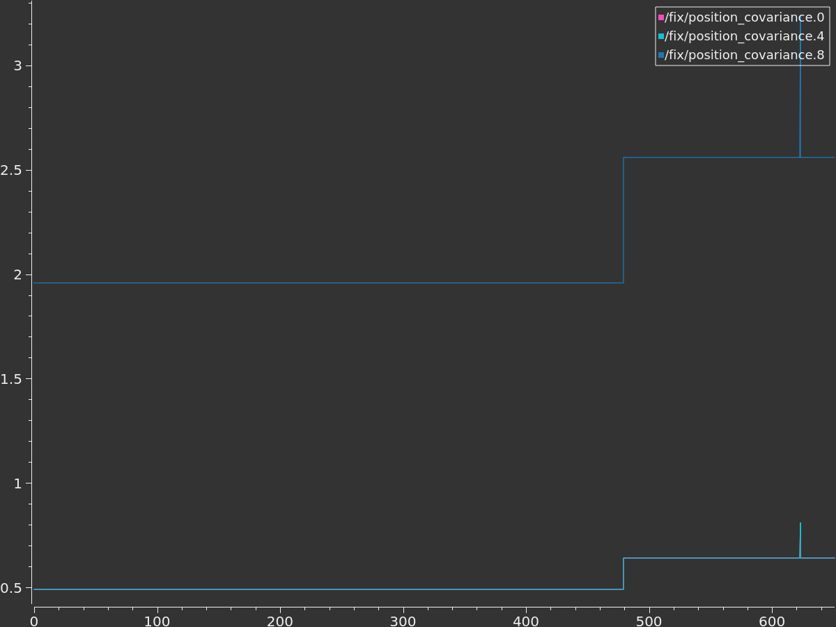
The covariance output from nmea_navsat_driver looks a bit higher than I would expect from a unit with an RTK fix. I will need to check how it’s calculated as the high values of covariance could be an issue when fusing in wheel odometry in later stages of the integration.
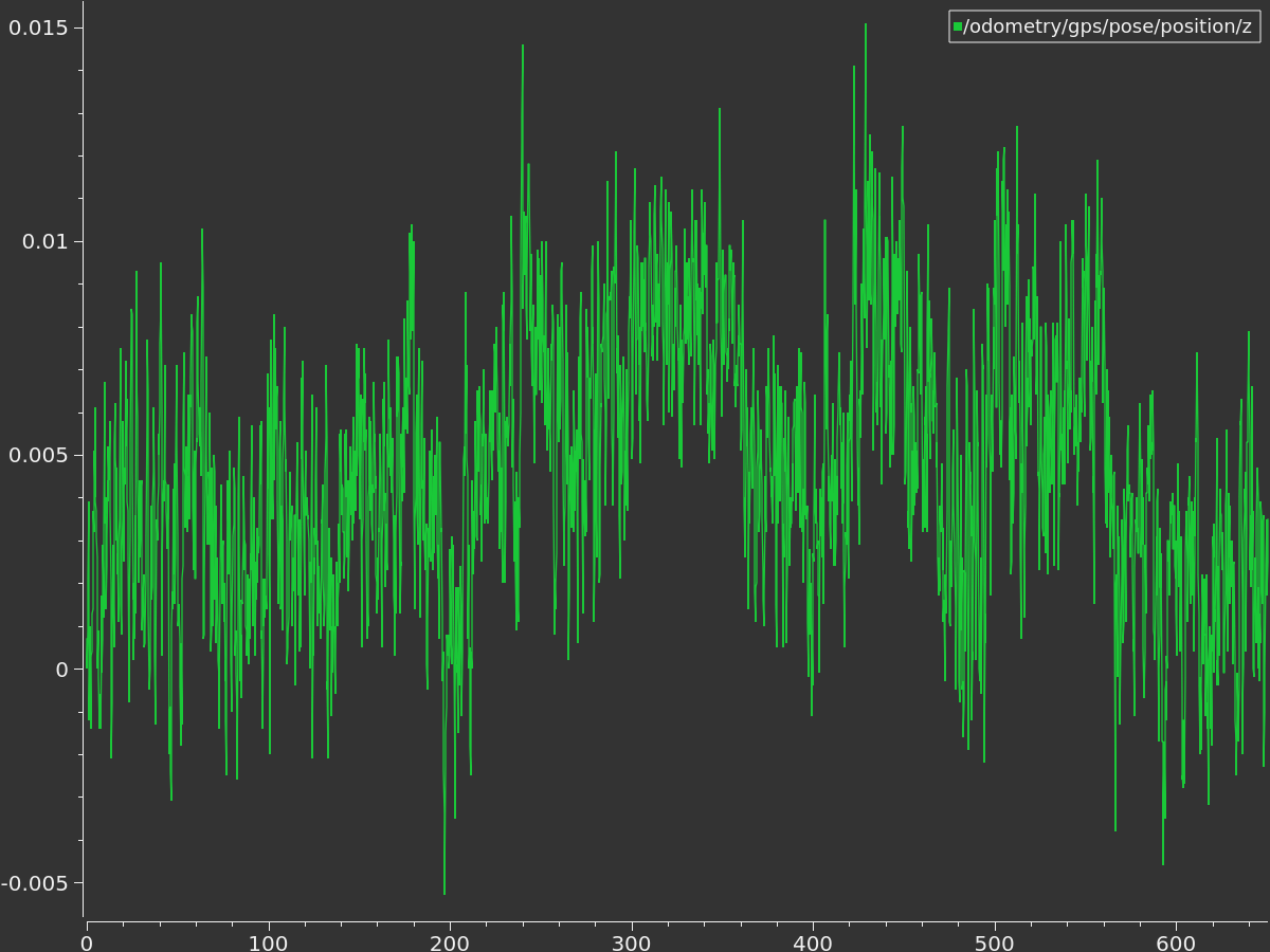
What is interesting in the static test is the precision of height data that is not far away from what’ve seen for XY-axes:
Dynamic tests
The dynamic tests I performed suffer from one issue: I don’t have any reference information to compare the measurements against. For having the absolute idea about the quality of measuerements some proper geodetic methods should be used (for example a total station).
For this test, I traced a roughly rectangular path and walked around it carrying the rover unit. The measurements won’t be very consistent as I was holding the whole rover setup in hand while walking the marked path. Here is the GNSS odometry position:
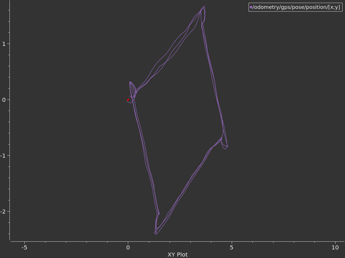
The data looks very good, I believe once covariance is addressed this setup should pretty much work out of the box on any mobile robot as the global EKF providing map->odom transform.
Closing thoughts
When I mentioned Plug&Play in the title of this blog post I wasn’t kidding. I like how Septentrio made it easy to work with these modules. Everything I needed to set-up was explained in the videos, with these tutorials rarely exceeding 3 minutes. The quality of support and documentation that you get from Septentrio is also top-notch.
At the same time there are some features that I will be looking forward to testing in the future:
- Using SECORX positioning service and/or NTRIP service integration for corrections
- Enabling PPS and NTP server on the mosaic’s side
- Switching from NMEA output to SBF (Septentrio Binary Format) and testing ROSaic driver or mosaic_gnss_driver
- Upgrading the firmware on Septentrio and running some more test on increased update rate (so far I’ve been outputting position at 10 Hz)
- Eventually testing mosaic-H with dual antenna setup for receiving heading information
Now, what would be a really, really interesting test? Taking this setup, adding a quality IMU and a LiDAR unit to it, creating a very precise 3D mapping module.