Making a 3D mapping prototype with ROS
In my previous post I’ve shared some of my experience working with Septentrio Mosaic X-5 dev kits. After seeing some good results with that hardware I’ve decided to try to use them with some other hardware to realise a prototype that I had in mind for quite some years. In this post I’m going to describe what I did to get a first prototype working and share some tips for anyone who would like to replicate them.
The idea
I’ve been interested in developing a proof of concept system for mapping (either using SLAM or other methods) for at least 7 years now (it might be slightly related to the fact that I was developing something similar for my master thesis). Since I’ve had a chance to work with RTK GNSS units (firstly with ArduSimple and then with Septentrio’s solutions) the logical next step was to start integrating more sensors. Before we get into the nitty-gritty details and the final demo I run let’s take a look at the first prototype of the idea:
The design
Here is the list of hardware that I had access to for this project:
- 2x Septentrio Mosaic X-5 dev kit - precise GNSS modules in RTK setup
- Xsens MTi-630-DK - AHRS (a precise magnetometer was a must-have for the prototype)
- Livox Mid-40 LiDAR
- Two Mikrotik routers
Sensors
Livox Mid-40
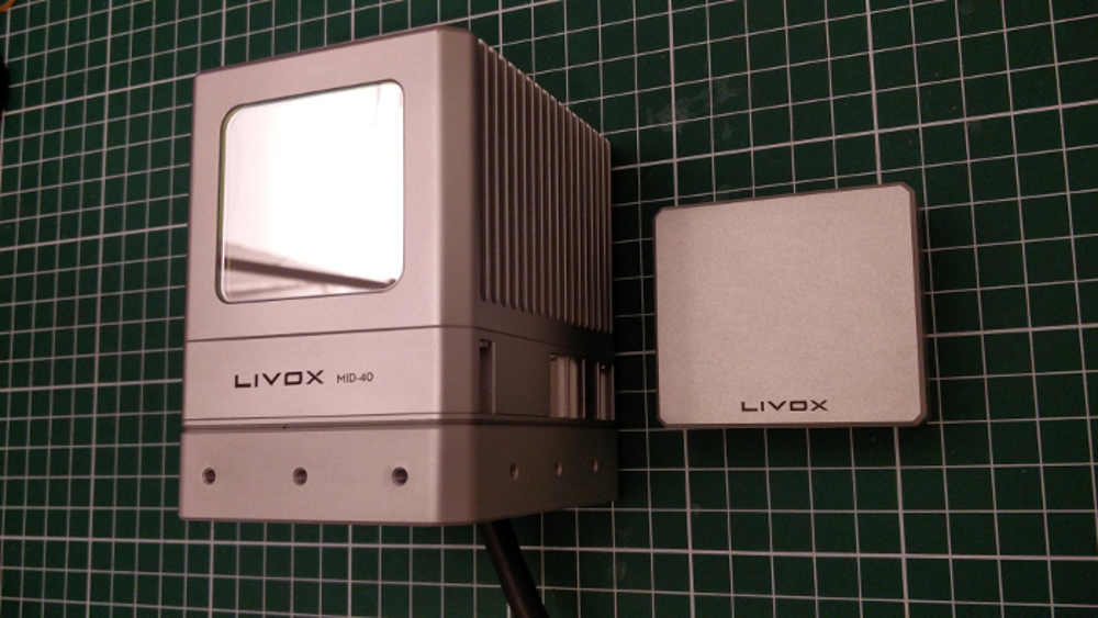
I’ve received Mid-40 from Livox over 2 years ago and described my initial thoughts in this blog post. Having a neat scanning pattern was an interesting feature for the prototype. With a single plane LiDAR, I would have to move the prototype quite a bit to gather data, with Mid-40 I could instantly tell if the data was good because I would immediately see the features in the scans.
Xsens MTi-630-DK
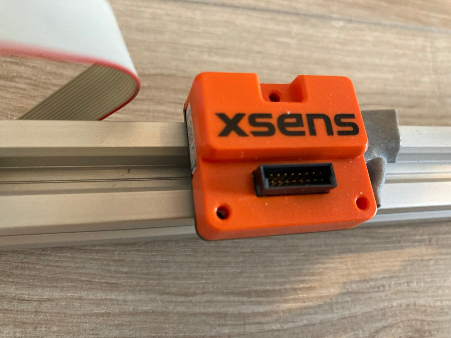
Xsens was very kind to lend me an evaluation unit of MTi-630-DK for my demonstrator, even though the initial phase of the project took me way longer than anticipated. The MTi-630 is an Attitude and Heading Reference System (AHRS) as it runs on-board sensor fusion algorithms that estimate absolute 3D orientation, in this blog post I’m using IMU and AHRS interchangeably. The main feature I was after in the IMU/AHRS was as precise globally referenced heading as I could get. The better the AHRS the less angular drift I would expect to see in my data.
In the video I’ve shared in the previous section you can see me testing the first prototype in a room running just the MTi and the Mid-40. I used double sided-tape to attach the unit to the top of the LiDAR, created a simple URDF file with correct offset between frames and voila! By slowly rotating the LiDAR in place I was able to scan the room. Let’s take a look at it again:
Do you see an issue with the 3D map being created? As the LiDAR is turning left you can notice that the new points appear shifted with regard to the points that were initially captured.
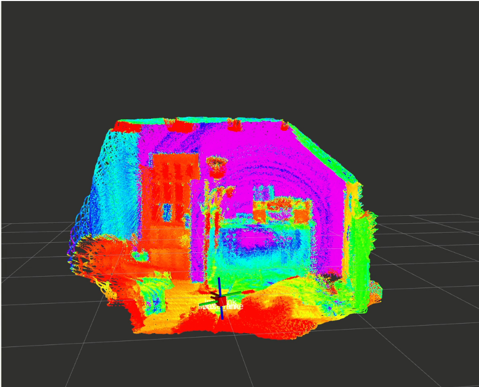
In my hastily prepared prototype, I assumed that the Mid-40 origin is in the centre of the LiDAR, while according to the docs the origin of the LiDAR is flushed with the front face of the unit. Oh well, it’ll be fixed in the next iteration that will include the next sensor.
And if you are thinking now “hey, Mat, won’t placing the sensor so close to some moving parts, that are undoubtedly magnetic and surely inside the LiDAR, affect the sensor readings?” then you are right. Even though I couldn’t see it when looking at RVIZ data, much later I noticed that turning on LiDAR affected the magnetometer reading that was fused by the AHRS for the orientation estimation.
Septentrio Mosaic X-5
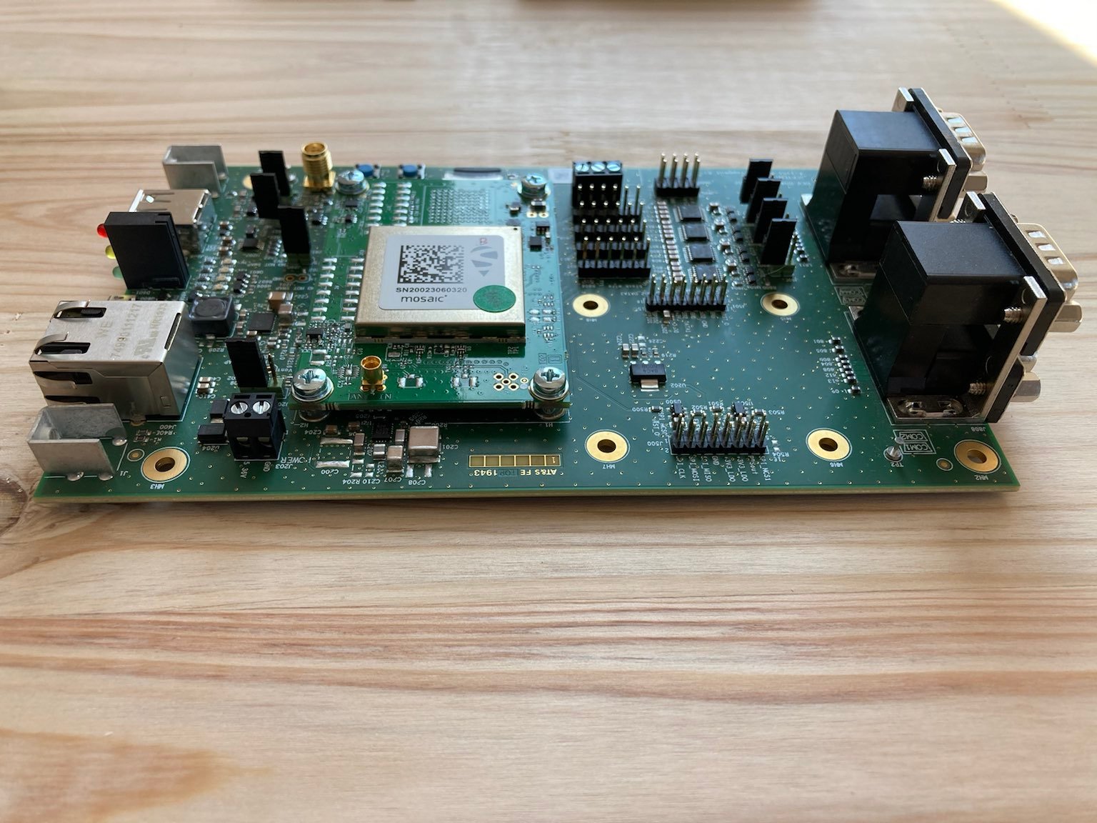
I’ve used Septentrio dev kits in exactly the same way that I’ve described in the previous blog post. Just as a quick recap: one unit was functioning as a base station, sending corrections to the rover unit that I’ve mounted on the prototype. All exchanging information through WiFi.
Having very precise location information is the core problem to solve for this prototype. Another approach that could be used would be to try to run SLAM, but this would require more processing power and most likely a LiDAR with a more repeatable pattern and higher field of view.
Putting it all together
Hardware
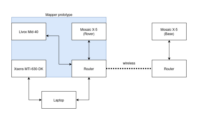
Here is how I connected everything up when it comes to hardware:
I’ve mounted all the components on a frame built from 2020 V-slot profiles, making sure I have enough room for anything I might want to add in the future:
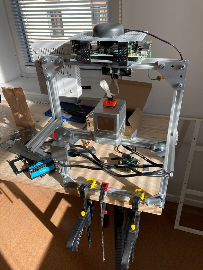
The LiDAR and the Router were both powered off a single 3S LiPO battery, while the GNSS unit and the IMU was powered from my laptop’s USB ports.
There are two issues with this setup:
- I planned to use my laptop for processing and could not be bothered setting up a smaller processing unit
- The unit weighs too much to be comfortably carried for long periods, even if a 2nd person carries the laptop
The best thing about this setup was the flexibility for mounting things. I had enough space to keep adding any hardware I might have needed or wanted to try out. After all, my only goal in these experiments was to prove the concept.
Software
For my prototype, I’ve used ROS Melodic, since that’s the version I’m still mostly using, and I had it on my machine. Something I love ROS for is the existing packages and libraries. What I think is interesting, is that for the prototype I didn’t need to write any software, I was just able to put together a bunch of existing packages by having the right configuration (perhaps having a good idea of what I’m doing helped too).
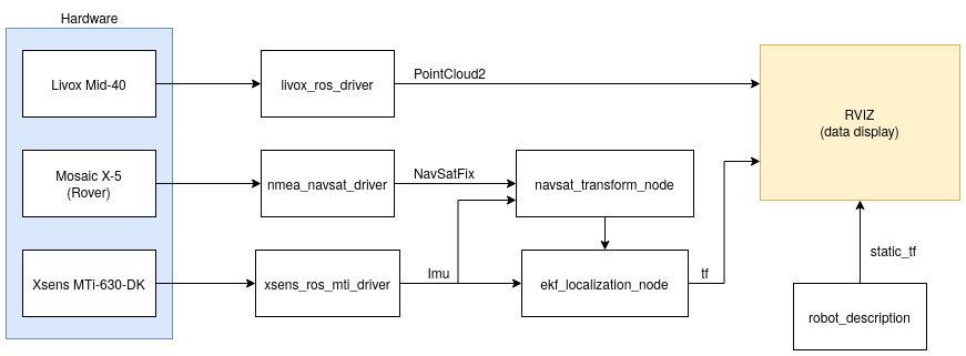
To make testing easier I’ve created a xacro file that defined all the dimensions and components, together with their position. Bein able to visualise the setup made testing easier as I could double check the state estimation matches reality:
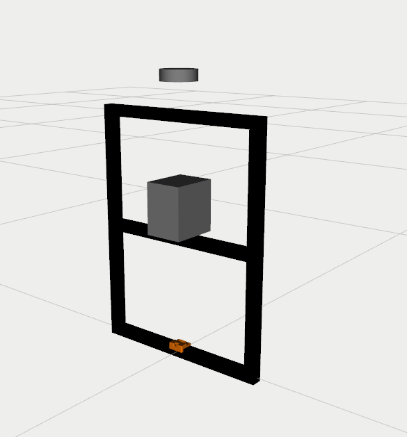
This data on where sensors are with respect to one another is used throughout the system. Not only it allows to accurately represent the PointCloud in RVIZ but it also is used by EKF nodes for checking the relative positions between elements.
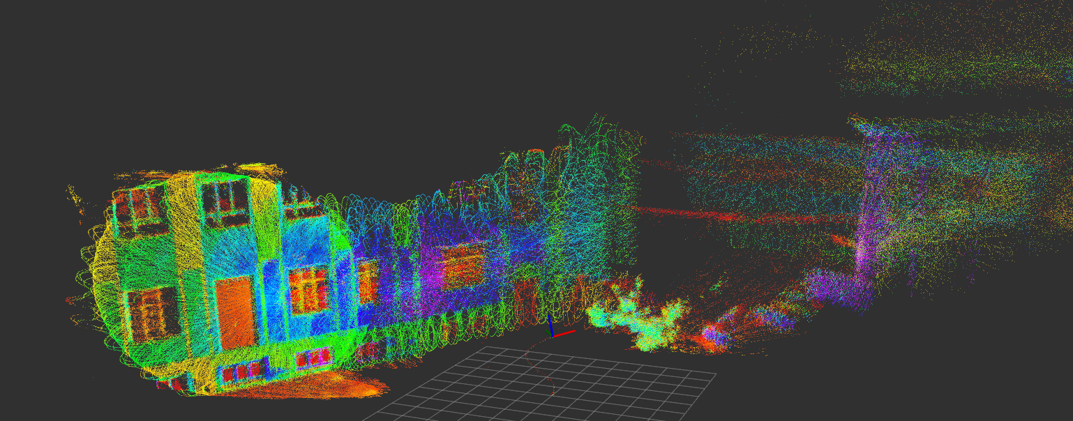
The localization is a classic ROS ekf stack described in detail on these pages. Running this EKF allows us to get an estimated position of the robot in a fixed coordinate frame (map or odom). Setting the Fixed frame to map in RVIZ then allows us to visualised all the LiDAR points as you can see here:
This is one of the 2 mapping runs I’ve run with this hardware, with a hand-tuned heading offset. This result is exactly what I need to prove the concept. If you know Pareto principle I firmly believe that in 20% of the time, I’ve shown 80% of the system functionality. The remaining 80% time required is a solid grind, with lots of tuning and field trips to create something viable.
Lessons Learned
I’ve learned a tonne in this project, so naturally, there is some brain dump:
- V-Slot 2020 profiles are amazing, if you work with them I highly recommend 3D printing or sourcing some caps that you can place on the profile ends. They are quite sharp, without caps you don’t want them anywhere near surfaces you care about
- Start work with some computer that will run everything and have a small screen, running everything on the laptop, and carrying a heavy prototype is not a great idea
- In my experience so far, every trial takes me between 3-5 hours, mostly because I’m in the city, and quiet places with good views of the sky are hard to come by. If you are using ROS then record bagfiles and use them for tuning the system (especially localization and IMU integration)
- Use checklists - on one occasion I had all the cables I needed by pure luck. I highly recommend using a checklist for field packing and performing experiments. Ensuring your GNSS unit is connected to the router when testing will surely save you some debugging time as well!
Further thoughts
For a project like this timing is everything. Both the LiDAR and the IMU that I’ve used support sync input, while Septentrio’s Mosaic can easily be configured to provide sync output. Instead of using EKF as I did, perhaps the data could be used directly with very little sensor fusion. This would probably be the approach I would have taken if I was developing a handheld module.
Instead, I’m way more likely to put this kind of hardware on a mobile robot of some kind, making sensor fusion a much more likely requirement as the precise position and orientation would be used for other aspects than mapping.
Next steps?
Right now I don’t have any plans to pursue this project further as it is. I’m glad that I was able to prove the concept but I don’t have a use case for such a device. I’ll use these learnings in future robot integration projects. If someone wants to build off the work I’ve described here for an open-source project then I’ll be more than happy to help out, but for now, it’s time to focus on other ideas that I have in the pipeline!