IMUs and LiDARs - Not Uncommon Pitfalls
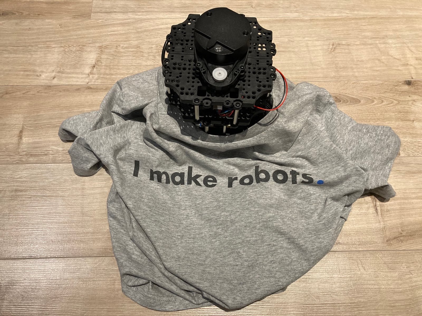
While preparing my ROS2 course on mobile robots I was not able to find quality information about basic sensors that can be used for mobile robots and the most important considerations on using them. In this short blog post, I’ll discuss some of the issues I have come across while using IMUs and LiDARs in tens of robotics projects.
IMUs
If you are working in mobile robotics it’s pretty much given that you will use an IMU on your robot. Over the years I’ve worked with multiple sensors such as:
- MPU6050
- Bosch BNO055
- PhidgetSpatial Precision
- Xsens MTi-630-DK - last used for my blog post on 3D Mapping
When choosing a sensor, your number one consideration will be most likely price, if you are on the market for some sensors the IMUs above will most likely introduce you to the whole range of prices. Please don’t consider the list above as advice, as everything depends on the fine details of your project. Most likely you will want to take a look at such features as:
- Update rate - for wheeled mobile robots ~50Hz is enough, for UAVs 100-500Hz should do depending on aircraft type
- Whether the attitude fusion happens onboard the sensor
- Available interfaces - USB is probably the easiest if you are thinking of using ROS
- Resolution, maximum readings, gyro drift etc.
- Calibration requirements - more on this in the next section
IMU gotchas
In my experience so far, IMUs are the sensors causing the most trouble when integrating them on mobile robots. Let’s go through some common pitfalls one by one:
1. Magnetic interferences
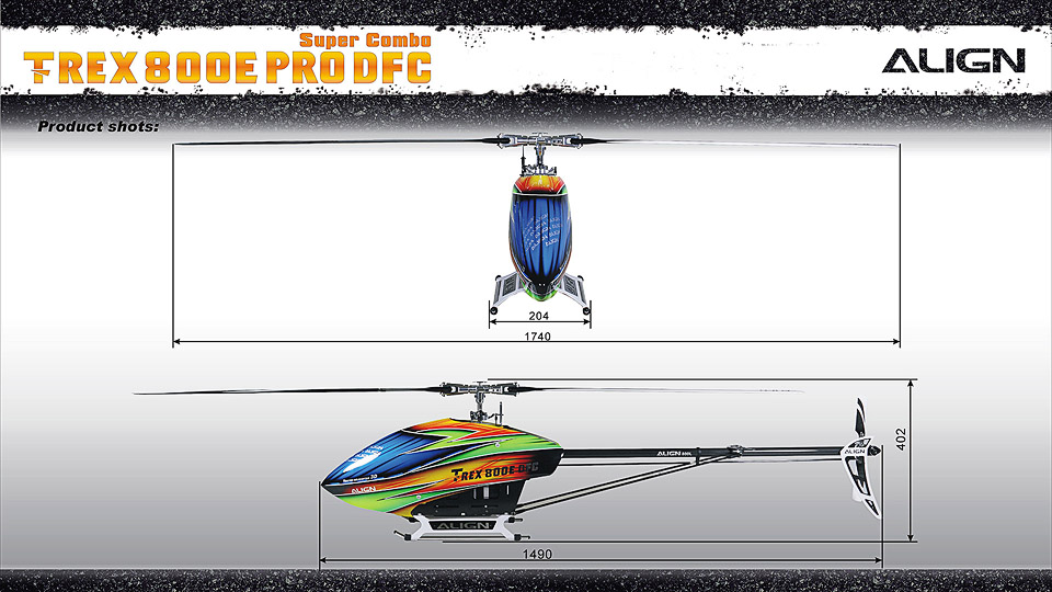
In my first job, we were integrating a drone autopilot with an onboard IMU on a helicopter platform. After many days of trial and error, we were not able to tune the heading controller that would make the helicopter keep a fixed heading while in the air. Only by accident, we’ve noticed lots of noise in the heading component in the IMU data and then when we were landing the aircraft we’ve noticed that, actually, these magnetometer errors have a period and it’s tied to the rotation speed of the main rotor! We have not seen this behaviour in the smaller model, which lead us to the discovery that in the model we had used ferrous metal rods in the blades! That would explain the noise.
HINT: If you are using a magnetometer in your robot - always move it as far away as possible from sources of the magnetic field. The most common source would be moving ferrous metals, actuators (magnets!) and high-current wires.
2. Vibration
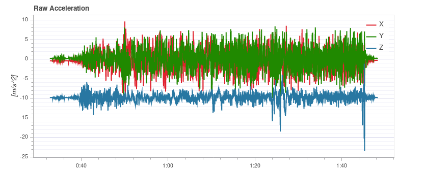
Your robot most likely vibrates. The amplitude of the vibrations will depend on materials used, type of terrain and the drive train (among many other factors). In drones, we had a rule that when you plot all acceleration axes, and X or Y axis measurements are touching the Z-axis measurements during hover then your vibration levels are too high.
Transferring these rules onto mobile robotics:
HINT: If your robot drives on a flat planar surface and you see acceleration readings overlap between X/Y and Z axes then you definitely need to dampen the vibrations.
To dampen these kinds of vibrations you could use rubber offsets or thick double-sided tape.
3. Axes definition
This point is highly specific to software, but many robotic systems I’ve been working on had issues with wrongly defined IMU axes at one point or another.
HINT: Always double-check the IMU axes defined in your software vs. the axes of your physical device.
4. Calibration
Some IMUs will require you to perform calibration (usually rotating the sensor in some way in all-axes), however, some IMUs will not store this information (looking at you BNO055). Once your IMU is mounted on a target system, you might not be able to rotate it along all axes, so you need to make sure this will not cause you some issues.
LiDARs
If you are reading this article from top to bottom (why wouldn’t you?), then here starts the fun! With LiDARs we are entering a space of ‘smart robotics’, where our robots can start reasoning around their environments and can know where they are.
Without going into too much detail (Wikipedia has got you covered for this), with LiDARs we are talking about a light pulse is emitted and we calculate the time it takes for it to come back (in some cases we might look at the phase shift of light too).
When we talk about LiDARs on the market we will find the following types:
- Single point distance sensors (e.g. Terabee TeraRanger Evo, Lightware SF11/C) - provide single point measurements
- 2-D scanners (e.g. RPLidar A1, Hokuyo UTM-30LX) - provide single plane measurements
- 3-D scanners (e.g. Ouster, Velodyne Puck) - provide measurements in multiple planes
- Scanners with non-repeating patterns (e.g. Livox Mid-40) - provide measurements as a non-repeating pattern
The choice of the sensor should depend on your application, interfaces you want to support, the processing power available etc.
LiDAR gotchas
Before I worked with LiDARs I didn’t know that light can be so annoying! Here are some things you might (but hopefully won’t) come across.
1. Eye fatigue
Now, I don’t have any evidence for this, but on numerous occasions, I have experienced eye fatigue while working with LiDARs. It feels like your eyes are a bit numb, my colleague describe the feeling as ‘pain, but without the pain component’. Technically, most LiDARs you will come across will be eye-safe, but I would still recommend not keeping them at your eye level. If anyone knows any research about long term issues that could result from these, please feel free to let me know.

2. ‘Flip effect’
This is one of the issues that you will rarely come across but if you do it will be a huge pain in the ass to rectify. I’m actually not aware of anything you can reliably do to filter this kind of data in all cases. What happens here, is that the sensor reports a way smaller distance than it should, as shown in the picture below:
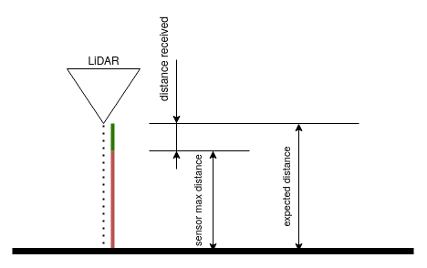
The real distance of the sensor is red + green (expected distance), but the sensor report just the green distance. The only way to fix this problem that I know of is to update sensor firmware.
3. Field of view shenanigans
Your LiDAR emitter will have a certain field of view (most likely a circular one, about 1-3 degrees). Looking at the picture below, there is a sensor with a field of view, and an object that is only partially in view. What distance would you expect the sensor to provide?
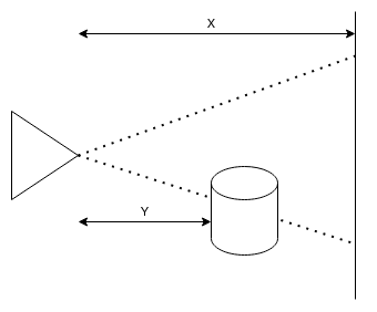
The answer is: it depends on your sensor! Some will provide the first return (Y), some will provide both Y and X (that’s how you can map tree canopies with LiDAR) and some will average all distances within the field of view providing the result Y < Result < X.
Whether any of these will be a problem for you depends entirely on your application.
4. Maximum distance vs. environment
The datasheets of LiDARs will usually specify the maximum distance, but you will not necessarily see the same maximum distance in your application. Usually, the specs provided are for targets with some defined reflectivity. If you direct your sensor at a black target (low reflectivity), you probably won’t be able to reach the maximum distance shown in the datasheet.
Another issue that will hamper your measurements are outside conditions. The chart below will show you which wavelengths are overly present in solar radiation.
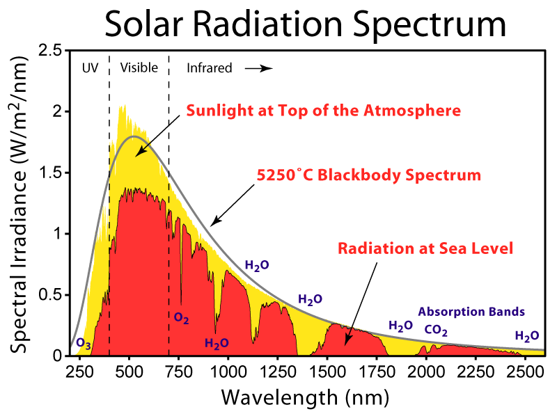
Most likely, the sensor of your choice will fall into one of the valleys in the chart. If the manufacturer of your sensor is not providing the wavelength of the sensor. consider it to be a red flag. Combining everything we’ve covered in these subsections, you might learn that having a sensor operate in full sun, looking at tall grass might yield the maximum range that will be suboptimal for your application.
Outro
This about sums it up, when it comes to some pitfalls I’ve run into when working with LiDARs and IMUs. Robotics being robotics there are hundreds of other things that can go wrong in your setup, hopefully with some patience and good detective work you’ll be able to get to the bottom of issues you come across in your setups.
Now, let’s make some robots!